Overview
This article explains the different types of cables used for connecting the Control Unit (CU-4E/CU-4D) with the Gen 5 / Gen 6 family of sensors. For the list of all Gen 5 /Gen 6 cables, refer to the Cable Spec Sheet.
The Control Unit (CU-4E) applies to the following models:
- Fixture Mount Control Unit for 0-10V drivers: CU-4E-FMH,
- Nipple Mount External/Internal Control Unit: CU-4E-NME/NMI, for North America only
The Control Unit (CU-4D) applies to the following models:
- Fixture Mount Control Unit for DALI drivers: CU-4D-FM, for use in the EU only.
The following sections are categorized based on the type of Gen 5 sensor connected to the Control Unit (CU-4E/CU-4D).
- Overview: Gen 5 Sensors Cabling Matrix
- Control Unit (CU-4E/CU-4D) with Micro Sensor (SU-5E)
- Control Unit (CU-4E/CU-4D) with High Bay Sensor (SU-5S-H)
- Control Unit (CU-4E/CU-4D) with Ruggedized Sensor (SU-5S-xRx)
- Gen 5 Sensors 8-Pin Assignments
- Line Diagrams
Overview: Gen 5 Sensors Cabling Matrix
The Sensor Cabling Matrix table provides an overview of the cables needed to connect a Gen 5 sensor to the Control Unit. The table is categorized based on the type of Gen 5 sensor and Control Unit model.
The maximum cable length between an Enlighted SU-5 sensor (SU-5E or SU-5S) and a CU-4E/CU-4D control unit can be a 300’ CAT5E cable. Multiple cables from different sensors going to different CUs can share the same raceway or cable tray without signal degradation or cross-talk. Maintain the separation of circuits from class 1 wiring per the requirements of the AHJ.
Note: All Enlighted cables are plenum-rated as indicated by the CMP (Communications Multipurpose Plenum), 600 VAC, #24 AWG CAT 3 cables, and UL numbers are indicated on the cable.

Notes:
Control Unit (CU-4E/CU-4D) with Micro Sensor (SU-5E)
The Control Unit (CU-4E) applies to the following models. The DALI Fixture Mount (CU-4D-FM) is for use in the EU only.
1. CU-4E-FMH and CU-4D-FM with Micro Sensor
2. CU-4E-NMI with Micro Sensor
3. CU-4E-NME with Micro Sensor
1. CU-4E-FMH and CU-4D-FM with Micro Sensor
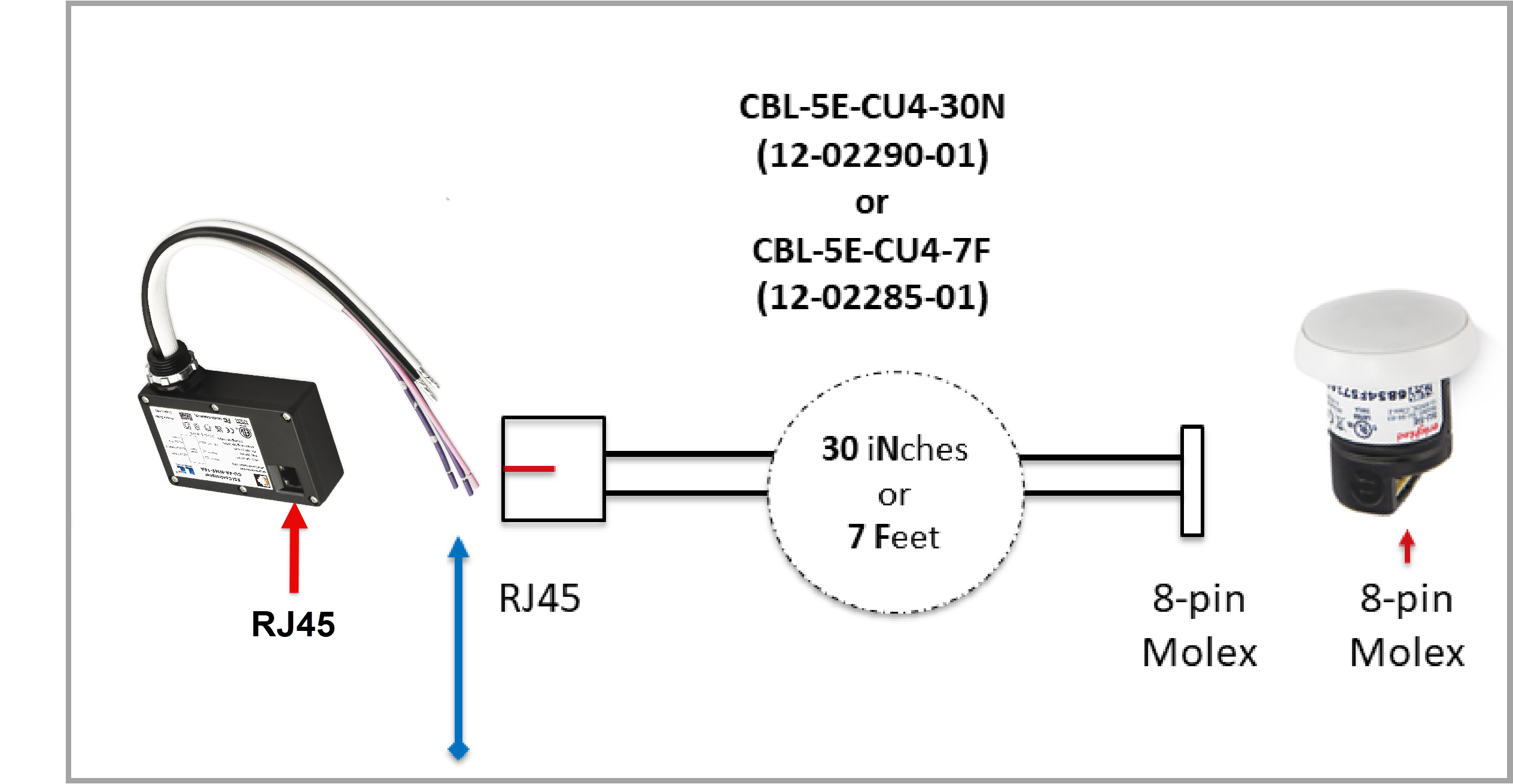
Use any of the following cables for connecting the Control Unit with the Micro Sensor (SU-5E). View Cable Assembly diagram.
- 30-inch sensor cable, (CBL-5E-CU4-30N): 12-02290-02
- 7-foot sensor cable, (CBL-5E-CU4-7F): 12-02285-02
- 15-foot sensor cable, (CBL-5E-CU4-15F): 12-03267-01
- 25-foot sensor cable, (CBL-5E-CU4-25F): 12-03268-01
- 50-foot sensor cable, (CBL-5E-CU4-50F): 12-03248-01
- 75-foot sensor cable, (CBL-5E-CU4-75F): 12-03269-01
- 100-foot sensor cable, (CBL-5E-CU4-100F): 12-03270-01
The above cables have an 8-pin Molex connector on one end that connects to a sensor and an RJ-45 connector that connects to the CU-4E/CU-4D on the other end. The cables, along with their terminal connectors, are shown below.

30-inch Sensor Cable

7-foot Sensor Cable
15/25/75/100-foot Sensor Cable
Refer to the line diagram SU-5 and CU-4E with one or more 0-10V Drivers (02693-05) for details.

Refer to the line diagram SU-5 with CU-4D with one or more DALI Drivers (02945-02) for details.

2. CU-4E-NMI with Micro Sensor
You will need the following cable and connector for the Nipple Mount Internal (CU-4E-NMI) with the Micro sensor.
- 12-inch sensor cable, (CBL-5E-CU4-12N): 12-02289-02, View Cable Assembly, and
- Female RJ45 coupler, (CPL-RJ45): 27-00379-01. View Diagram.
This cable has an 8-pin Molex connector on one end that connects to the sensor and an RJ-45 connector on the other end to the CU-4E.

12-inch Sensor Cable

Female RJ-45 Coupler (CPL-RJ45)
3. CU-4E-NME with Micro Sensor
The Nipple Mount External (CU-4E-NME) with the Micro sensor requires the following cable:
To extend cable length, connect CPL-RJ45 (or standard CAT5e coupler) to RJ-45 end of the cable and connect standard RJ45-to-RJ45 straight-through cable of the desired length between the CPL-RJ45 coupler and CU-4E. It can be purchased readily.
Refer to the line diagram SU-5 and CU-4E (NME) with one or more 0-10V Drivers (03155-01) for details.

4. CU-4A-NME-16A with Micro Sensor
The Nipple Mount External (CU-4A-NME-16A) with the Micro sensor requires the following cable:
To extend cable length, connect CPL-RJ45 (or standard CAT5e coupler) to RJ-45 end of the cable and connect standard RJ45-to-RJ45 straight-through cable of the desired length between the CPL-RJ45 coupler and CU-4A. It can be purchased readily.
Refer to the line diagram for more details;
Control Unit (CU-4E/CU-4D) with High Bay Sensor (SU-5S-H)
To connect the Control Unit (CU-4E-FMH, CU-4D-FM, CU-4E-NME/NMI) with the High Bay Sensor (SU-5S), you will need the following cable.
- 7-foot RJ45 cable, (CBL-RJ45-RJ45-7F): 12-02627-02. View Cable Assembly
- Optional Female RJ45 coupler (CPL-RJ45): 27-00379-01 to extend the cable length. View Diagram.
This cable has an RJ-45 connector connected to the CU-4E and an RJ-45 connector connected to the sensor on the other end.

7-foot RJ45 Cable
Standard RJ45-RJ45 patch cables of the desired length can be used instead of the above cable. However, please note that a short-body RJ45 connector is recommended at the sensor-end to allow for a shorter cable bend radius if the sensor is flush-mounted against a flat surface. The maximum cable length between an Enlighted SU-5 sensor (SU-5E or SU-5S) and CU-4E control unit can be 300’ CAT5E cable.
Refer to the line diagram Gen 5 Sensor with Control Unit: SU-5 and CU-4E with one or more 0-10V Drivers (02693-05) for details.

Refer to the line diagram SU-5 with CU-4D with one or more DALI Drivers (02945-02) for details.

Control Unit (CU-4E/CU-4D) with Ruggedized Sensor (SU-5S-xRx)
The following cables are needed to connect the Control Unit (CU-4E-FMH, CU-4D-FM, CU-4E-NME/NMI) with the Ruggedized sensor (SU-5S-xRx). However, no cable is required if the Ruggedized sensor's 20-inch sensor cable length is sufficient to connect.
- 7-foot RJ45 cable, (CBL-RJ45-RJ45-7F): 12-02627-02. View Cable Assembly
- Optional Female RJ45 coupler (CPL-RJ45): 27-00379-01 to extend the cable length. View Diagram.
This cable has an RJ-45 connector connected to the CU-4E and an RJ-45 connector that connects to the sensor on the other end. The cable, along with the terminal connectors, is shown below.
7-foot RJ45 Cable
To extend cable length, connect CPL-RJ45 (or standard CAT5e coupler) to RJ-45 end of the above cable and connect standard RJ45-to-RJ45 straight-through cable of the desired length between CPL-RJ45 coupler and CU-4E. It can be purchased readily. The maximum cable length between an Enlighted SU-5 sensor (SU-5E or SU-5S) and CU-4E control unit can be up to 300' CAT5E cable.

Control Unit (CU-4E) with Ruggedized Sensor (SU-5S-xRx)

Control Unit (CU-4D) with Ruggedized Sensor (SU-5S-xRx)
Gen 5 Sensors 8-Pin Assignments
Gen 5 sensors have the following pin assignments:
| Pin | Description |
| Pin 1 | Not Connected |
| Pin 2 | Not Connected |
| Pin 3 | Dimming Channel 2 |
| Pin 4 | GND |
| Pin 5 | VDD |
| Pin 6 | Dimming Channel 1 |
| Pin 7 | RX Data |
| Pin 8 | TX Data |
Cable Assembly

7-foot RJ45 Cable Assembly

Female RJ45 Coupler, (CPL-RJ45), 27-00379-01

Line Diagrams
Refer to the following line diagrams to understand the connection between the Gen 5 sensor and Control Unit (CU-4E/CU-4D). The Control Unit (CU-4E) applies to the models: CU-4E-FMH, CU-4D-FM, CU-4E-NME/NMI. Refer to the CU-4 Spec Sheets for details.
Recommended articles:
Downloads:

