The Enlighted Hard Ceiling Mount Carrier (product code HCMC-SU-5E) is a flexible mounting solution for Gen 5 and Gen 6 Micro Sensors. The Hard Ceiling Mount Carrier provides adequate framing around the sensor when the Micro sensors need to be installed in a hard ceiling or inside a light fixture diffuser where a minimal radial profile is needed.
Spec Sheet
This article includes steps for installing the Hard Ceiling Mount Carrier for the following sensors:
Gen 5 Micro Sensors, 8-pin and 2-wire (product codes SU-5E, KIT-SU-5E-D)
Spec Sheets for Gen 5 Micro Sensors
Install Guides for Gen 5 Micro Sensors
Installation of the Hard Ceiling Mount Carrier for Gen 5 Micro Sensors
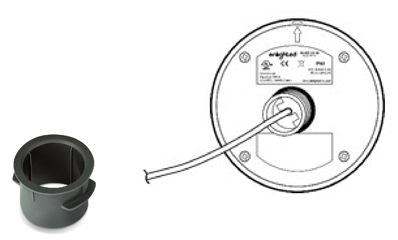
To install the Microsensor with Hard Ceiling Mount Carrier:
- Drill a 7/8" diameter hole in the diffuser where the sensor is to be mounted.

- Insert the Hard Mount Carrier into the hole.
 
- Insert the 8-pin end of the sensor cable through the Hard Ceiling Mount Carrier and connect it to the SU-5E sensor.


- Push the entire assembly into the hole.

Gen 5 Ruggedized Sensors (product codes SU-5S-HRW/LRW, SU-5E-LR)
Spec Sheets for Gen 5 Ruggedized Sensors
Install Guides for Gen 5 Ruggedized Sensors
Installation of the Hard Ceiling Mount Carrier for Gen 5 Ruggedized Sensors
Four mounting options are available:
- Option 1: Mounting the Sensor directly on Drywall/Sheetrock/Ceiling tile (with or without J-box backup)
- Option 2: Mounting Sensor directly into 1" EMT or Rigid Conduit
- Option 3: Mounting Sensor onto 3/4" EMT conduit stub
- Option 4: Mounting Sensor onto 3/4" rigid conduit stub
Option 1: Mounting the Sensor directly on Drywall/Sheetrock/Ceiling Tile (with or without J-box Backup)
To install the Ruggedized sensor with HCM in drywall or hard top ceiling,
- Drill a 1" diameter hole where the sensor is to mount

- Stretch the HCM carrier to insert it over the sensor nipple in "normal" orientation with the flange facing towards the sensor.
- Connect the sensor cable to the ceiling cable, using the RJ-45 coupler.

- Glide the coupler and excess wire into the drilled hole.
- Press the sensor as far as possible into the drilled hole.

Option 2: Mounting Sensor directly into 1" EMT or Rigid Conduit
To install the Ruggedized sensor with HCM into a 1" Electric Metallic Tube (EMT) or Rigid conduit,
-
Stretch the HCM carrier to insert it over the sensor nipple over the sensor nipple in "normal" orientation with the flange facing towards the sensor.
- Connect the sensor cable to the cable from the conduit, using the RJ-45 coupler.
- Glide the coupler and excess wire into the conduit.
Note: Ensure that the cable is completely drawn out and not compressed at the end of the conduit.
- Press the sensor as far as possible into the conduit.
Option 3: Mounting Sensor into 3/4" EMT Conduit StubÂ
To install the Ruggedized Sensor into a 3/4" EMT conduit stub please make sure that you have access to the fixture side of the stub.
- Stretch the HCM carrier to insert it over the sensor nipple over the sensor nipple in "normal" orientation with the flange facing towards the sensor.
- Attach a ¾" EMT coupler to the end of the EMT conduit stub.
- Glide the sensor cable through the coupler and EMT conduit stub into the conduit body, J-box, or a fixture at the other end of the stub.
- On the fixture side of the stub, connect the RJ-45 connector or RJ-45 coupler with the extension cable from the sensor to the CU.

- On the sensor side of the stub, glide the excess wire into the conduit.
Note: Ensure that the cable is completely drawn out and not compressed at the end of the conduit.
- Press the sensor as far as possible into the coupler.
- Tighten the screw on the coupler if it is accessible. Ensure that the screw is not overtightened.
Option 4: Mounting Sensor into 3/4" Rigid Conduit Stub
To install the Ruggedized Sensor into a 3/4" rigid conduit stub, you must have access to the fixture side of the stub.
- Stretch the HCM carrier to insert it over the sensor nipple in "normal" orientation with the flange facing towards the sensor.
- Attach a ¾" EMT to rigid combination coupler at the end of the rigid conduit stub.
- Glide the sensor cable through the coupler and the rigid conduit stub into the conduit body, J-box, or fixture at the other end of the stub.
- On the fixture side, connect the RJ-45 connector or RJ-45 coupler with the extension cable from the sensor to the CU.
- On the sensor side, glide the excess wire into the conduit.
Note: Ensure that the cable is completely drawn out and not compressed at the end of the conduit.
- Press the sensor as far as possible into the coupler.
- Tighten the screw on the coupler if it is accessible. Ensure that the screw is not overtightened.
Gen 6 Micro Sensor, 2-wire (product code SU-6E-2W)
Spec Sheet for the Gen 6 Micro Sensor, 2-wire
Install Guide for the Gen 6 Micro Sensor, 2-wire
Installation of the Hard Ceiling Mount Carrier for Gen 6 Micro Sensor, 2-wire
To install the Microsensor with HCM:
- Drill a 7/8” diameter hole in the diffuser where the sensor is to be mounted.

- Insert the Hard Mount Carrier into the hole.

3. Connect the 2 wire end to the sensor through the Hard Ceiling Mount Carrier and connect it to the SU-6E sensor.

- Push the entire assembly into the hole.


